The RF in RFID: physical layer operation of passive UHF tags and readers
Daniel M. Dobkin
(revised Dec 2012)
4a: Old RFID Protocols
This page describes a couple of UHF passive tag protocols that have been superseded by the Class 1 Generation 2 protocol, but are informative to study for the lessons they carry about the different approaches that have been used to solve similar problems.
EPCglobal Class 0
The class 0 standard describes passive, write-once tags that are distinguished primarily by the use of a subcarrier modulation scheme for the tag-to-reader link. Tags manufactured by Symbol Technologies, Impinj, and some Avery tags, are generally compliant to EPCglobal's published standard, though note that the standard was never fully ratified and there is no compliance verification procedure. Many class 0 tags are configured as dual dipole tags: that is, the integrated circuit is connected to two distinct antennas, typically orthogonal to one another. Dual dipole tags are necessarily larger than the corresponding single-dipole tag, but in compensation they are much less sensitive to the polarization of the incident radiation than a single dipole. However, this is a characteristic of the commercial implementations and is not covered in the standard.
Note also that the standard doesn't cover writing a new electronic product code (EPC) to the tag. Symbol and Impinj both implemented field-writeable tags. Symbol's are called "class 0+" and Impinj's tags are known as "Zuma". These two implementations are supersets of the published standard, and are completely incompatible with one another in memory architecture and command definitions.
Before sending any data, the reader first goes through a turnon sequence to get the tags ready to go. First it sends some DC power, and then a series of synchronization pulses to help the tags set their clock oscillators to 2.25 MHz (see below). The whole process takes about 800 microseconds, after which the reader can send commands to the tags.
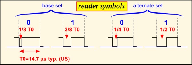
Passive tag modulations differ from typical radio communications schemes because the reader signal also powers the tag, so it is useful to have the signal be at its maximum value most of the time. The air interface for class 0 is based on pulse-width modulation for the reader-to-tag (forward) link. There are three basic symbols, shown below. (Note that the diagram shows the transmitted power of the reader vs. time; the actual signal is a modulated carrier wave at around 900 MHz.) A binary '0' is transmitted by turning the reader power down or off for a brief time, typically 3 microseconds in US operation, after which the power is turned back up for the remainder of the symbol. A binary '1' is send by turning the power down for a longer period of time, typically 6 microseconds. A special symbol, the null, is used to signal tags to change their state; this symbol occurs infrequently, and so the fact that the reader power is turned off for much of the symbol doesn't affect the tag power level much. The total time for each symbol is about 12.5 microseconds in US operation, corresponding to a data rate of 80 Kbps.
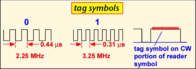
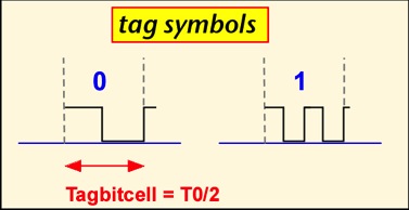
A specialized approach is employed for the tag-to-reader (reverse) link. The tag actually scatters its reply during the 'high' part of each symbol. The symbols themselves use sub-carrier modulated frequency-shift keying : the tag switches at a relatively high rate of either 2.25 or 3.25 MHz to send a binary '0' or '1'. The use of this sub-carrier modulation has some advantages: in essence, the demodulator gets to count a lot of edges for each tag transmission, so it is easy to tell which symbol was sent and corruption of a single edge due to e.g. noise or interference doesn't prevent the reader from distinguishing a '1' from a '0'. The relatively high frequency also means that the downconverted baseband signal contains information only in the region 2-4 MHz away from the carrier, where the phase noise of the local oscillator is typically small, so that good sensitivity is easier to achieve. However, the scheme encounters problems when many readers are present, because the tag reply is so far away from the carrier that it may lie right on the frequency transmitted by a neighboring reader. In Europe, even passive tags are regulated as transmitters, and the tag radiation may be centered outside of the fairly narrow bands allocated to RFID operation, causing compliance problems.
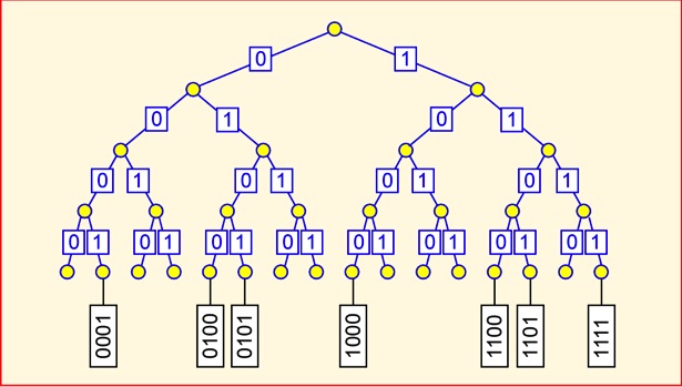
A notably simple approach is used to control access to the medium. To start with, the reader sends a command informing all the tags that can hear that it is going to execute a binary tree traversal. The reader then sends the null symbol followed by a binary '0'. All tags then backscatter the first binary bit of their ID. The reader can tell if a '1' or '0' was sent, though it can't say if more than one tag transmitted at the same time. If some tags send '1' and some '0' the reader may detect a collision, or it may simply randomly choose to see either bit. The reader then echoes the bit that it heard. Any tags that hear their bit stay in the traversal and send their next bit. Tags that don't hear their bit fall out of the traversal (transitioning to the MUTE state) and wait for another (null,0). If everything goes smoothly, by the end of the traversal only one tag is still participating (if all the tags have unique numbers), and all its bits have been read. By remembering which branches of the tree had responses, the reader should ideally be able to navigate only the occupied parts of the tree of all possible tags. For example, in the tree shown below, the reader might go down 0001 but wouldn't bother with 001... because no tag responded with a '1' at that bit.
The procedure above may still be very inefficient if a large number of tags with the same ID except for the last few bits are present: each traversal wastes a lot of time repeating the same path. The standard provides the option to use either a random number generated upon demand by each tag (known as ID0) or a short random number stored in each tag (ID1) instead of the tag's unique electronic product code (ID2). ID0 and ID1 are not guaranteed to be unique in a tag population, but in realistic populations the chance of duplicates is small. Another disadvantage of using ID2 for singulation is that since the reader echoes each bit, the reader sends the whole EPC of each tag. Readers can be heard from up to several kilometers away under the right conditions, whereas tags are hard to intercept from more than a few meters away.
Once a tag has been identified, it can be KILLED if the kill password is known. According to the standard, a successful KILL command results in a permanently non-functional tag. It's not really clear what good this does; retailers would be reluctant to kill a tag if the item it was attached to could be returned, and how is a consumer to know if a tag is really dead or merely temporarily out of commission? See RFID: Applications , Security and Privacy, eds. Simson & Garfinkel, for useful discussions of privacy and security issues.
Although the EPCglobal standard document treats class 0 tags as having a factory-written unique identifier not field-modifiable, in practice customers have found that it is often desirable to write a new ID, as well as other specialized data, to tags in use. Unfortunately, since the standard did not specify an approach to writing tags, the two primary vendors (Matrics -- now part of Symbol -- and Impinj) chose different and incompatible approaches.
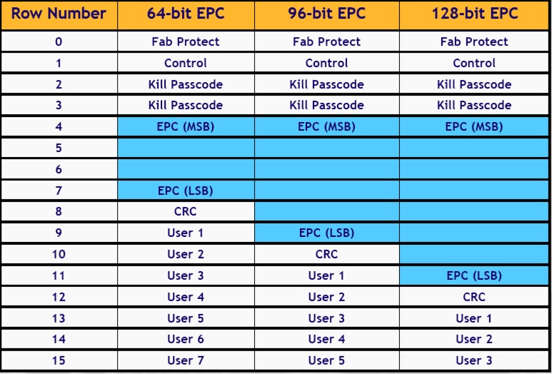
Zuma tag memory was organized in 15 rows of 18 bits each. Bit 0 was not used in most rows, and bit 17 is the row locking bit. The allocation of rows differed depending on the size of the tag's EPC, as shown in the chart. The first row, Fab Protect, must be set to the value 0997A (NOTE that the first character is binary and the remainder hexadecimal: that is, the row is x0 1001 1001 0111 1010, where x is the lock bit). If the lock bit is set high the tag is permanently locked.
Bit 17 of the control word, instead of locking the row, locks memory against writes. Bit 16 is the row lock. Bits 15-12 set the EPC size, and are 0101, 0111, and 1001, for 64, 96 and 128 bit tags. The remainder of the rows use bit 17 for row lock. The kill passcode is programmed into bits 16 thru 5 of two consecutive rows. Rows 4 through 14 contain the EPC, error check (CRC) and user memory.
Thanks to Chris Parkinson of IntegralRFID
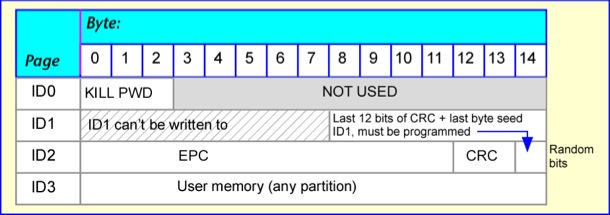
Class 0+ re-used the nomenclature of the class 0 standard to denote memory pages. Memory was organized into four pages, but not all of them could be written to. The ID0 page is used to record the KILL password. The ID1 page contains the random singulation code, but the code is generated from a seed rather than being written directly. The seed is the last 20 bits of the ID2 page. For a 64-bit-EPC tag this part of the page would not otherwise be used, but should be filled with 20 random bits. For a 96-bit-EPC (shown below) the seed bits overlap the CRC (error check). The last page, ID3, can be used in any fashion by the user.
EPC Global Class 1
The class 1 standard document describes a 'write-once' passive tag, though in practice tags can be written (at least) hundreds of times. Alien Technology, Avery, and Rafsec have produced large numbers of commercial tags that are substantially compliant with the standard, though it was never ratified and there is no compliance verification procedure. The tag-to-reader (forward-link) symbols are very similar to those used in class 0; in fact, the optional symbol set is identical.
The tag reply uses a simple frequency-shift keying scheme known as F2F: an edge in the middle of the symbol denotes a binary '0', whereas three edges denote a binary '1'.
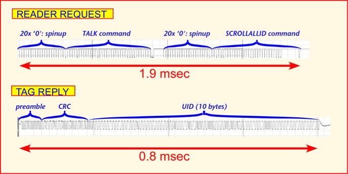
Unlike class 0, class 1 is a packetized interface in which the reader sends a full command, and then one or more tags may reply with either a few bits or a complete message. If one expects only one tag in the read zone at any given time, collision resolution can be skipped: the reader repeatedly sends the SCROLLALLID command, and any tag hearing it replies with the tag CRC and EPC. This 'global scroll' mode of operation is relatively fast; about 500 tags/second can in principle be read (though most of the reads will simply be repeat reads of the same tag). The reader can optionally add a TALK command at the beginning to make sure that tags are all active, and a QUIET command directed to a tag after it has been read to make it possible for other tags to talk. The first steps are shown below. The QUIET command is rather time consuming, since the whole tag ID must be sent as a 'filter' to ensure that only the desired tag stops talking. The whole procedure takes around 4 ms for a 64-bit tag, allowing around 250 tag reads/second, and works reasonably well when up to 4-5 tags are present near the reader.
When a large number of tags are simultaneously present in the read zone of a reader, a more sophisticated anti-collision algorithm can be employed, using the filter capability built into reader commands. Each command can contain filter bits, of any length up to the full length of the CRC+EPC, and starting anywhere in memory. Only tags whose EPC fits the filter will respond to the command. The PING command causes tags whose EPC's match the filter to respond by sending the next 8 bits of their EPC, and doing so within one of 8 reply 'bins', each marked by a special symbol from the reader, the choice of bin depending on the first three bits of the reply. When the reader believes that only one tag is replying in a bin, it can request the full EPC of the tag.

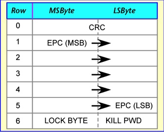
Class 1 memory organization is fairly simple: memory is organized in 7 or 9 rows of 2 bytes each. The CRC occupies the first row, the EPC (most-significant-byte first) the next five or seven rows. (The astute reader will note that this is two more bytes than are actually required to carry the EPC. The class 1 error check uses a sequence of 16 '0' bits after the EPC; curiously these bits are programmed into the tag even though the calculation is only performed by the reader, which could certainly insert the bits under program control.) The last row contains the lock byte, which is set to hexadecimal A5 to prevent further writing of the tag, and the kill password. Since the kill password is only 8 bits long, some commercial tags time out after a failed KILL attempt in order to prevent a dictionary attack, otherwise very simple since there are only 256 possible codes.
The 64-bit EPC map is shown below; the 96-bit map adds the requisite EPC rows. It is important to note that at least some class 1 tags are not rendered non-functional when KILLed, but merely erased.
Discussion
Both first-generation standards share some significant disadvantages. It is awkward to address a specific tag, particularly if you have erased the EPC in the course of assigning a new code to the tag. The use of a 16-bit CRC as the only validation of a tag ID means that on average one in 64,000 reads of random noise would produce an accidentally valid tag read -- a phantom or ghost tag. Class 0 tags have problems with large numbers of collocated readers due to the large frequency offset between the tag signal and the reader signal, and have no standard for field writeable tags. Class 1 singulation is relatively slow when a large number of tags are present. Both protocols have problems with late arrivals: tags that enter the read zone when a tag inventory has already started. Finally, class 0 and class 1 are mutually incompatible and approximately equivalent in applications and performance: if the goal is to achieve one global standard, two is one too many.
Solutions for these problems were implemented in the Class 1 Generation 2 standard.